- 26
Jan - 2020PCB/Board designs, Product Reviews
3 min | 15659Table of contentShowA few months ago, I was looking for a small digital signal oscilloscope (DSO) module, and last week I got a DSO138 DIY kit from DigitSpace. The oscilloscope is originally from the company JYE Tech, but as usual, there are a lot of copies.
The oscilloscope has a bandwidth of 200kHz, a maximum sampling rate of 1MHz and a maximum input voltage of 50Vpk that are sufficient for the applications that I am programming using ESP32 boards (more details here).
In this article, I include a quick review of the product and I list some upgraded products.
![IMG_2788.CR2.jpg]()
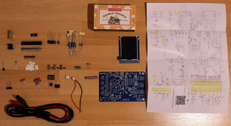
Fig. 1: Dissembled DSO138 Hardware
The following hardware is reviewed in this article:
DSO138 Review
In Fig. 1, you can see all the components that you get and what you need to solder. However, in some kits, there are some already soldered components. As you can see, in my case, the only soldered component was the STM32F103C8. I've to solder everything else including 0805 SMD resistors, an LM324 and two AMS1117, which wasn't a great deal for me, but it can be a problem if you are not used to it. I saw other kits, in which all the SMD components are soldered. Before you start, check the guide, and if you get it only in Chinese, check this link to get a version in English.
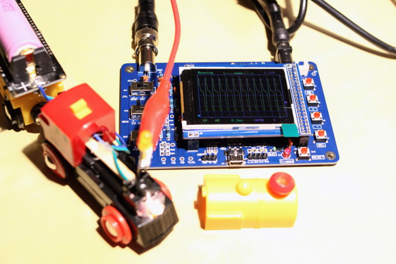
In Fig. 2, you can see that the DSO138 is a circuit board with a color LCD, on which all operating elements such as slide switches and buttons as well as sockets for signals and power supply are soldered. On the left side, you can see the selection of the input coupling (GND, AC or DC -CPL) and the amplitude (1V 0.1V 10mV multiplicator -SEN1 and (5, 2 or 1)/Div -SEN2). The resulting selection is shown on the button line of the RGB display (see Fig. 3 - SEN1:0.1V & SEN2:X5 = 0.5V on the display).
![IMG_2823.CR2.jpg]()
Fig. 2: DSO138 checking the voltage of the IoT BRIO Locomotive The RGB display has a resolution of 320x240 (QVGA) with a screen diagonal of 2.4" (6.1 cm), in which you see the signals and some other information. The module requires a 9V power supply (something annoying) and consumes about 120mA. The circuit diagram is also included in the package. Thus, it is possible to analyze the circuit. The 9V is converted to 5V (AMS1117-5V) and 3.3V (AMS1117-3.3V -which supplies the MCU-), and a simple voltage inverter generates a negative voltage, which is then regulated using a 79L05. Surprisingly, the positive voltages are regulated using SMD components and the negative using TO-92 packages.
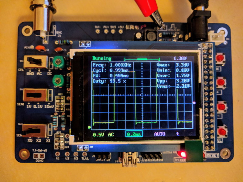
The MCU is a ST ARM Cortex-A3 (STM32F103C8) and its fast ADC is used. This offers a resolution of 12 bits and an input voltage range of 0-3.3V. Thus, 1.65V corresponds to the zero line on the display. However, you can use the switches of the right side to add or subtract an offset to horizontally center your signal. Using the switches, you can select the trigger mode (Auto, Normal or Single) and type (Rising/falling edge) and its position (1/2 of buffer size fixed) and the timebase between 10us/Div - 500s/Div. Additionally, holding the SEL button for about 2 seconds turns on/off the measurement readouts as shown in Fig. 3. Furthermore, you can freeze the waveform (record length: 1024 points) and move it horizontally.
![IMG_20200125_234931.jpg]()
Fig. 3: Measurement readouts Conclusions
The DSO138 is "a nice to have" oscilloscope and the "you get what you pay for" applies to it: you get a lot of electronics for little money, but you have to live with a few small quality weaknesses (switches, resolution). Very important: the DSO138 is not available as a pre-assembled/pre-soldered module: if you enjoy soldering, this can be your first low-cost oscilloscope. However, there is a new version of this DSO: DSO138mini, which has similar performance as the DSO138 but came with significant improvements in power supply (you don't need 9V anymore) and mechanical structure (sliders and switches), and if you have some more budget, check the WAVE2: a 2-Channel portable oscilloscope.
We use cookies to improve our services. Read more about how we use cookies and how you can refuse them.


Empty