 22
22
Oct - 2018Home Automation, MicroPython
5 min | 30146#MicroPython: Controlling Smart Power Outlets using an ESP32
Home Automation, MicroPython | 5 min | 30146
Today there is a wide range of offer for home automation devices. A lot of sensors, actors etc. can be connected to the cloud and be controlled using Google Home, Amazon Alexa, your smartphone, etc. There are a lot of companies offering low cost devices, e.g. Sonoff, Tuya, Teckin etc. Most of these solutions are based on ESP32 or ESP8266, and all of them send data to cloud solutions usually deployed on Amazon services, and the data is only accessible using the Android/iOS applications. They can be also controlled using voice commands over Google Home or Amazon Alexa devices.
Nice, but... my aim was to control these devices locally (using LAN and not Wi-Fi) and send the data to the Google Cloud Platform (GCP) to make some analytics later. To be clear, when you use the Android/iOS application (or Google Home/Amazon Alexa) and you switch on/off e.g. a smart power outlet, the application connects with the company server in which the smart power outlet is registered and it sends the command. Then, the server sends back the action to your smart outlet. An exception is Amazon Alexa that sometimes connects directly to the devices (e.g. Belkin switches / Philips Hue), when you are at home on the same network (Wi-Fi). That's why you can re-program the Sonoff devices using Sonoff-Tasmota and then, you don't need a cloud connection anymore. However, if you use Google Home, this is not possible.
To sum up the aim of this post: Using this tutorial, you'll be able to control locally (LAN) most of the low-cost smart power outlets using an ESP32 programmed in MicroPython. Additionally, you can use the available data to do some analytics.
Here the code:
![Python]()
Code: https://github.com/lemariva/SmartUPy Note: Application like home assistant allows you to make this too, but you need at least a Raspberry Pi to run it, and that means power consumption. That's why, I like to do this with an ESP32 and of course, using MicroPython!
Hardware and Software
Important note: This doesn't work with Sonoff devices, for those you can use Sonoff-Tasmota. This only works with devices known as "Tuya-like" one (Tuya Inc. is the company). I use the Teckin outlets (see the article photo). If you want to check, if your power outlets are compatible, they should have the port
6668opened. To check that:>>> nmap <<ip-address>> -p 6668 [...] Host is up (0.13s latency). PORT STATE SERVICE 6668/tcp open ircIf you don't have the
nmapapplication and you are on Windows, look at the Nmap Network Scanning tool. On Ubuntu type on a terminalsudo apt-get install nmap.Key extraction
To get the status and data of the devices you don't need any key, but to control the devices, you need to use a key in order to encrypt the data/commands using AES and some MD5 (if you are looking for a MD5 MicroPython class, check the repository). I am going to explain how to extract using Android devices. A more detailed guide can be found here. This key is in the Android application and you can get that, if your Android is rooted. If not, you can monitor the communication when you use the application, and you can get the key too:
- Usually the Tuya smart outlets uses the Smartlife (or similar) application.
- Install it, and register your device(s) as usual.
- Then, you need to install a network capture application.
- There are a lot of them, I used one called Packet Capture, but it is not at the Play Store anymore. Then, I've installed SSL Capture and that worked too.
To capture the traffic between the Smartlife application and the company server, you need to follow these steps:
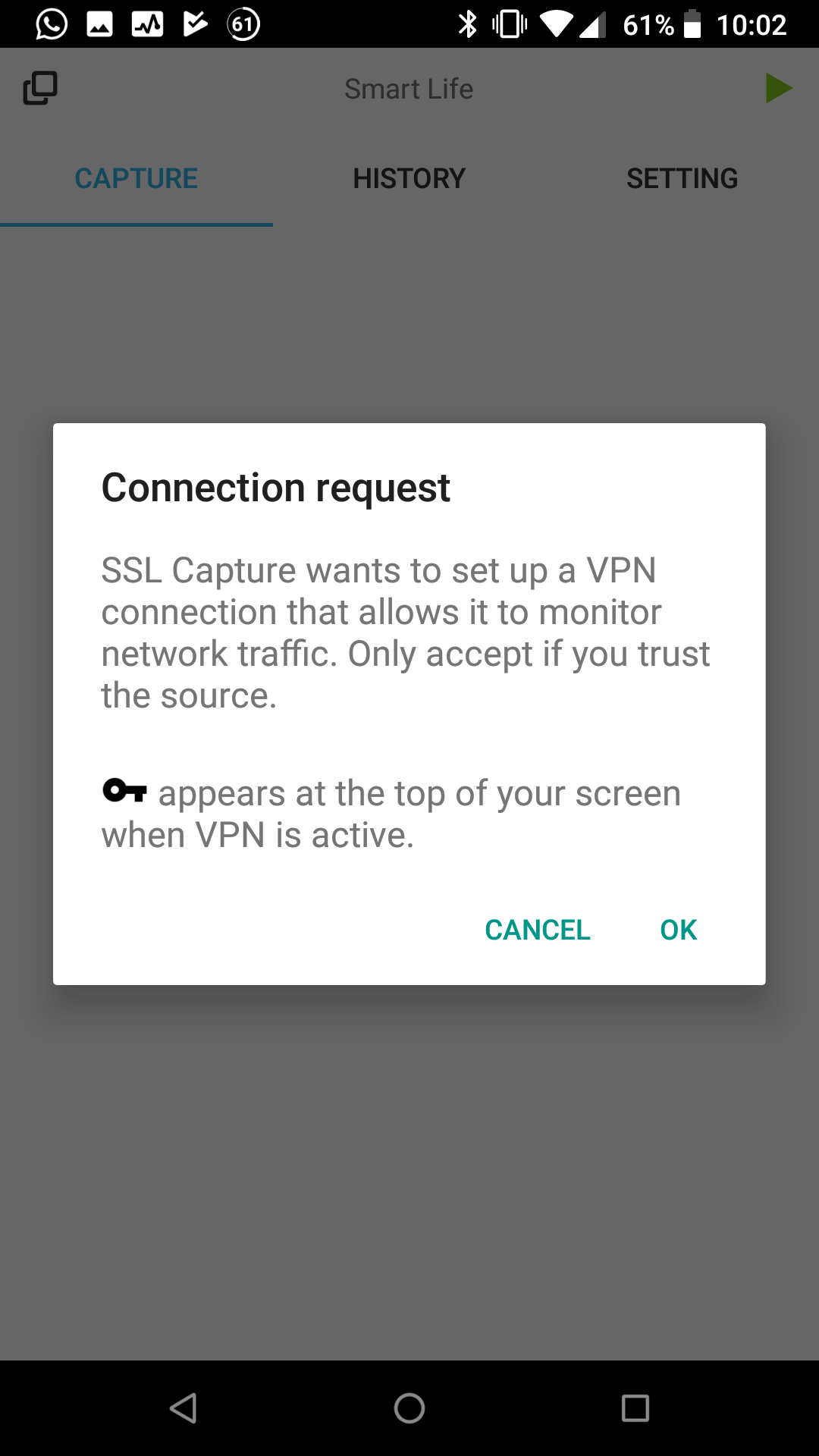
Open the SSL Capture application. It requires 2 permissions:
- Storage > save captured data.
- VPN certificate > install it to bridge the SSL communication (see Fig. 1).
Configure the capture filters (see Fig. 2) with the upper-left corner icon.
- You need only to capture the traffic of the SmartLife application, then select only this one.
Start the traffic capture (upper-right play icon).
Open the Smartlife application and switch on/off the device that you want to control with the ESP32.
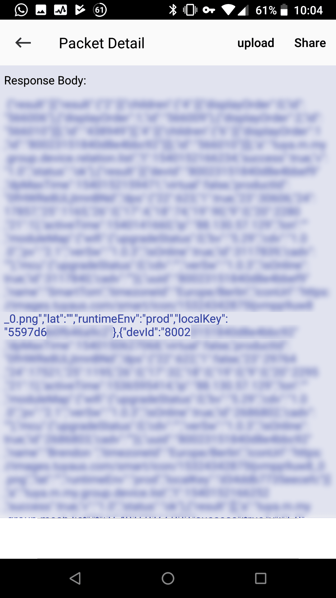
Go to the SSL Capture application and look for the captured data to find something like Fig. 3. You need to extract the
localKey, and you can get also thedevIdif you want to.
![VPN Packet Capture]()
Fig. 1: Installing VPN certificates ![Packet Capture Filter]()
Fig. 2: Capture filter setup ![LocalKey & devId]()
Fig. 3: Device devIdandlocalKeyDIY
After getting these values, you can program the ESP32 using MicroPython to control your power switches following these steps:
- Install MicroPython on your ESP32. If you need help, check this tutorial.
- Clone the SmartUPy repository.
- Modify the following variable in
main.py:- WiFi access data:
ssid_: Wi-Fi SSID, where your power outlet is also connected.wp2_pass: WPA2 password for the selected Wi-Fi.- Power outlet data in json structure
devices:name: Name for you to identify the outlet.devId: ThedevIdthat you obtained before.devIp: IP address of the power outlet on your LAN. You can get that from your Wi-Fi router.lokalKey: Thelocalkeythat you got before.
Upload the code to the board and that's all. You don't need all the files from the submodules (folders). You need the following:
ESP32MicroPythonfolder:md5hash.pymaes.pytimeutils.py
MicroWebSrvfolder:microWebSocket.pymicroWebSrv.pymicroWebTemplate.py
You can delete the other files if you want to save some space.
If you are using a ESP32-WROOM, I have some bad news for you, the RAM is not enough to run the rev1.2 (with webserver) and you need to cross compile the files using
mpy-crossto reduce memory usage.I take the following part from this post:
To do that, you need to use Linux (sorry Windows users) and clone the repositories:
- ESP32: micropython/esp32
Then, go to the folder
mpy-crossusing a terminal, and typemake. Wait a couple of seconds/minutes. Then, you can compile the python files using./mpy-cross <filename.py>to get the.mpyfiles.Then, load only the
.mpyfiles not the.pyfiles! Otherwise, the board tries to load the.pyand you get the same error again.You need to cross-compile at least the files listed above (inside the folders) and the
smartoutlet.pyfile too. You can optimize the code if you compress the.html,.pyhtml,.cssand.jsfiles too.I'm going to add a Webserver to the ESP32 to control the power outlets. But for now, you can control them using the PyMakr console (or you can fork the repository and extend it).Done!The following functionalities are available:
- This is the
outletarray:outlet = [] for j in range(0, len(devices)): outlet.append(OutletDevice(devices[j]['devId'], devices[j]['devIp'], devices[j]['lokalKey'])) These are the available methods e.g. for outlet number
0:outlet[0].turn_on(): switches on the power outlet.outlet[0].turn_off(): switches off the power outlet.outlet[0].set_timer(20): if the outlet is off, it will be turn on in 20 seconds, otherwise, if will be turn off in 20 seconds. The method's argument is an integer.outlet[0].status():you get ajsonas e.g. the following (it depends on the power outlet):{ 'dps': { '25': 1165, '24': 17857, '9': 0, '22': 623, '23': 30606, '1': True, '21': 1, '20': 2284, '18': 75, '19': 86 }, 'devId': '80023151840d8e4bbef9' }in my case, the parameters mean:
1: the actual status (True=On, False=Off).18: the actual mA consume.19: the actual W consume.20: the actual V.
If you have more information about the other parameters, leave me a comment.
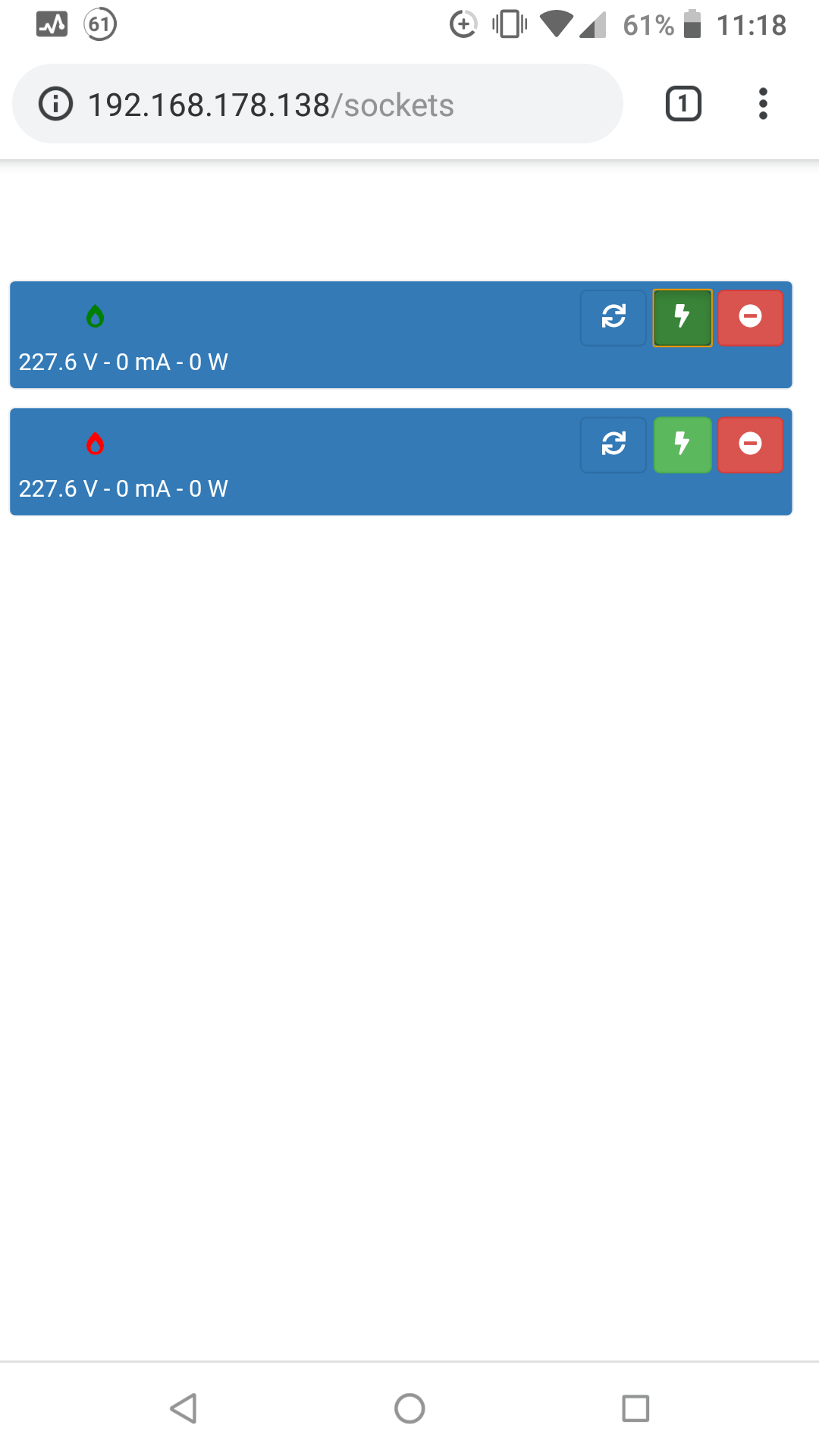
Webserver
I added a webserver to control the devices. Look in your WiFi router for the IP address of your ESP32 and connect to it using your smartphone or PC. It looks like Fig. 4. The first button updates the power outlet status (e.g. 227.6 V - 0 mA - 0 W and the green/red color of the flame), the second button turn on the socket while the last one turn it off.
![Webserver]()
Fig. 4: Webserver to control your Smart Power Outlets Acknowledgements
The code is basically based on: https://github.com/clach04/python-tuya
We use cookies to improve our services. Read more about how we use cookies and how you can refuse them.


")


")


Empty