") 31
31
Dec - 2020M5Stack, Raspberry Pi
7 min | 711724#Raspberry Pi HQ Camera: Autofocus for the Telephoto Lens (JiJi)
M5Stack, Raspberry Pi | 7 min | 711724
Table of contentShowThis tutorial opens the series of articles about "Project JiJi" and describes how to add autofocus to the 16 mm Telephoto Lens mounted on the Raspberry Pi HQ Camera. In the past months, I've been working on a project to add autofocus to the lens and this is the result:
Adding some background to this: The Raspberry Pi Foundation offers different Raspberry Pi Camera modules since 2013. The first module (5-megapixel) was produced in 2013, and an 8-megapixel module upgrade (v2) was released in 2016. Both models have visible light and infrared versions. This year (2020), the Foundation launched the HQ Camera. This is a 12-megapixel High Quality (thus HQ) camera (Sony IMX477), which adds the possibility to use a lens with CS-mount. It is a great upgrade, but the lens and the camera lack autofocus up to now.
If you are impatient, you can find the hardware design, firmware and software on the lemariva/rPIFocus and lemariva/uPyFocus repositories. But, you should come back and read the tutorial until the end, so that you can understand how it works, and if you want to, you can also cooperate on this project!
Software and Hardware
This section includes the software and hardware needed for this tutorial.
DIY: Project JiJi
In this article, I will explain how to build the project yourself. I won't go deeper in detail. These will be covered in future articles.
Hardware: PCB ordering, soldering, and mounting
As you may have already noticed, to add autofocus to the camera, you will need to order a PCB and solder and mount some parts. In the Github repository, under the folder `pcb`, you'll find the schematic as well as the board files for the PCB. To open those files, you'll need Eagle. Eagle is still free for hobbyists, thus, download and install it to open the files. You can export Gerber files using this export-to-gerber tutorial.
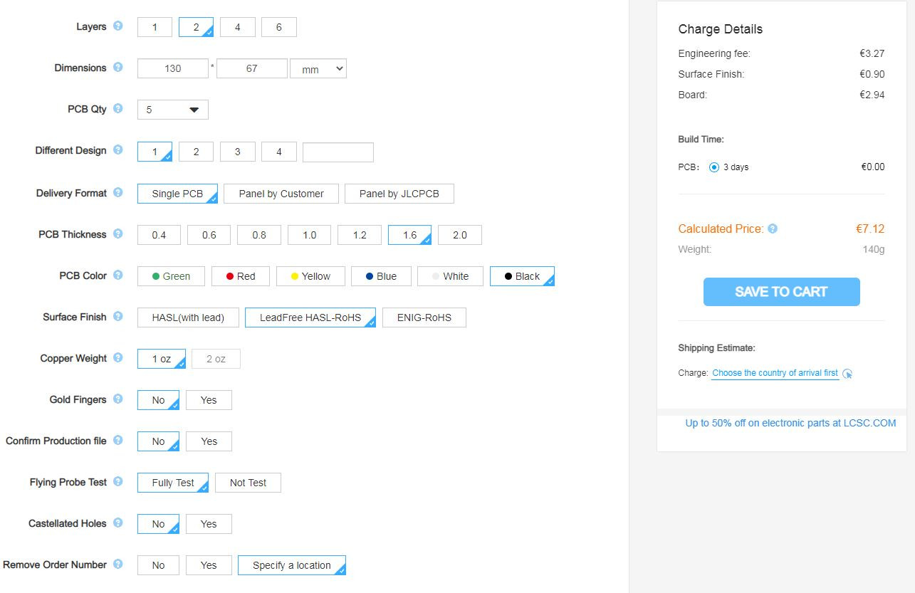
To simplify the process for you, I also added the Gerber files that you can directly send to your PCB provider. I use and recommend jlcpcb. They are fast, cheap, reliable and the quality of the boards is pretty good. Check out the setting and costs for this project in Fig. 1. Don't forget to select the LeadFree HASL-RoHS surface finish!
![jlcpcb settings]()
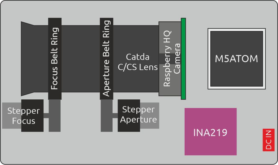
Fig. 1: jlcpcb settings for this project.I designed the PCB for people with two types of skills: advanced and basic. So, if you're a pro, grab your solder and solder every element (ICs) for yourself, or, if your skills are basic, don't worry, grab your solder and solder the small hobbies boards that you can buy from the selection above. Two steppers rotate the focus and aperture rings. They are controlled by the M5Stack ATOM, which also measures the steppers' currents and offers an RestAPI to send the commands (see Fig. 2 for an basic PCB schematic).
![Simple PCB schematic]()
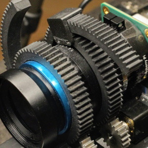
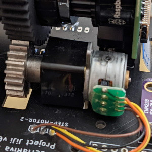
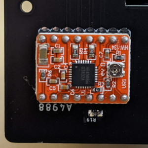
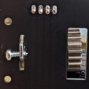
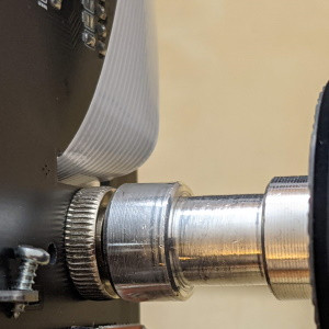
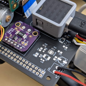
Fig. 2: Simple PCB schematic.Fig. 3 to Fig. 8 show you some close photos of the design to help you to mount the elements. Fig. 3 shows you how to mount the aperture and focus belt rings. They usually have a standard of 0.8 mm pitch. So the motor pinions should be compatible with that. Fig. 4 shows the mounted motor. Check the cable color - or the order! They are connected to the A4988 drivers (Fig. 5) and that's the right connection. Otherwise, the driver won't be able to switch the electromagnets in the right sequence and the motor won't rotate. I planned a cut on the PCB so that the pinion distance to the belt ring can be modified and the motor can be fixed as shown in Fig. 6 (using a 2.5 mm screw) - not the best way, but it works ;). To fix the camera to the board, I used a 3/8 inch screw and an adapter to mount that to a tripod (see Fig. 7). The screw fixes the camera to the board. The camera tends to rotate, and it releases the screw. If that's the case, you can fix it using the two 3mm holes on the left of the camera base (see Fig. 8) with an e.g. rectangular piece of wood over the board. Finally, you need to mount the INA219 and two pinheads for the M5Stack ATOM Matrix. The INA219 measures the current of the steppers, which are used to identify the rotational limits of the focus and aperture rings. Therefore, after booting, the system calibrates itself and it doesn't require encoders to measure the steppers positions.
![Focus and aperture ring belts]()
Fig. 3: Focus and aperture ring belts.![Motor connection and gear mounting]()
Fig. 4: Motor connection and gear mounting.![A4988 Motor stepper driver]()
Fig. 5: A4988 Motor stepper driver.![Motor fixing]()
Fig. 6: Motor fixing.![Camera fixing / tripod adapter]()
Fig. 7: Camera fixing / tripod adapter.![INA219 and M5Stack ATOM matrix]()
Fig. 8: Camera rotate fix option.![INA219 and M5Stack ATOM matrix]()
Fig. 9: INA219 and M5Stack ATOM matrix.As you can see in Fig. 9, there are some ICs, capacitors, and resistors that aren't assembled and also two cables (red and black). The cables supply 7.5V for the motors. The ICs, capacitors, and resistors are planned to provide 5V and 3.3V to the M5Stack, A4988 drivers, and the INA219. Currently (in that Fig. 9), they are supplied via the USB cable connected, on one end, to the M5Stack, on the other, to the Raspberry Pi. So, you have two ways to supply the system :). But, yes, you need two power suppliers: one for the steppers (7.5V) and one for the Raspberry Pi (5V). The 5V on the board (via ICs) won't be able to supply the Raspberry Pi. Sorry, but I didn't want to use bigger ICs for that.
M5Stack Application
As I described before, the M5Stack ATOM Matrix controls the motors and offers a RestAPI to receive the commands. The M5Stack application is programmed in MicroPython. If you haven't heard about MicroPython, you can check this tutorial: Getting Started with MicroPython on ESP32, M5Stack, and ESP8266. MicroPython is a lean and efficient implementation of the Python 3 programming language that includes a small subset of the Python standard library and is optimized to run on microcontrollers and in "constrained environments". The application is located lemariva/uPyFocus.
So, follow these steps to upload the application to the M5Stack:
- Flash MicroPython to the M5Stack as described in this tutorial.
- Clone the lemariva/uPyFocus repository:
git clone https://github.com/lemariva/uPyFocus.git - Open the folder
uPyFocuswith VSCode and rename theconfig.py.sampletoconfig.py. - Open the file and add your Wi-Fi credentials in this section:
wifi = {
    'ssid':'',
    'password':''
}
The M5Stack needs to connect to your Wi-Fi so that the Raspberry Pi (also connected to your Wi-Fi/LAN) can find it and sends the commands to control the steppers.
- Upload the application to the M5Stack.
After uploading the code, the M5Stack resets and starts with the calibration routine (check video section: nnn). Take note of the IP that the M5Stack reports while connecting to your Wi-Fi. You'll need that to configure the Microservices Application.
Docker and docker-compose on Raspberry Pi
The application that runs on the Raspberry Pi is a microservices application. That means different services are orchestrated to offer an application. The orchestration is performed by docker-compose and the services are containerized using Docker.
To install Docker on the Raspberry Pi, just type the following on a Terminal:
curl -sSL https://get.docker.com | sh
sudo usermod -aG docker pi
If you want to learn more about Docker on Embedded System, just read this tutorial: Tutorial: Docker on Embedded Systems (Raspberry Pi & Beagleboard)
To orchestrate the services, you need to install
docker-compose. This can be done by typing:sudo pip3 -v install docker-composeUsually, you need to install these dependencies:
sudo apt-get install -y libffi-dev libssl-dev
sudo apt-get install -y python3 python3-pip
sudo apt-get remove python-configparser
Memory Disk (optional)
To take photos faster, you can create a disk on RAM. A RAM disk offers faster access to the data compared to an SD card or a connected USB disk. Thus, this allows the application to reduce the time between photos. To do that, you need to create a folder by typing on a Terminal:
sudo mkdir /mnt/ramdiskThen, you need to modify the
/etc/fstabfile and add a line at the end of the file:sudo nano /etc/fstab ### add the following line at the file's end: tmpfs /mnt/ramdisk tmpfs nodev,nosuid,size=50M 0 0Then, you can mount it using:
sudo mount -aTo ensure that everything is working, just reboot your Raspberry Pi using:
sudo rebootTo display the newly created drive and check it use the following command.
df -hMicroservices Application
The services of the microservices application are the following:
- webapp: it provides the frontend application (webserver). It is programmed in Angular.
- backend: it communicates with the frontend via a RestAPI (Flask server), controls the camera, sends the signals to the M5Stack to control the motors, sends the signals and data to the other services to identify objects and take photos. Basically, it is the core service. It is programmed in Python.
- obj-detector: it receives an image over UDP and identifies the object on it and returns a JSON message. It is programmed in Python. It uses TensorFlow and connects to the Coral USB Accelerator to process the data in real-time.
- photo-service: it receives a signal via RestAPI (Flask server) to take photos and it processes them to create HDR photos. It is programmed in Python and it uses Celery for multitasking/non-blocking response to the RestAPI.
- redis: Celery uses this service to schedule the tasks.
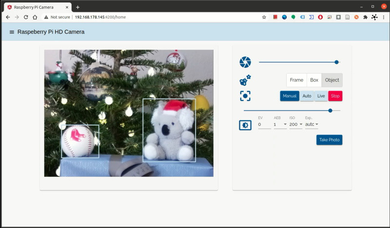
![Webservice Microservices Application]()
Fig. 10: Webservice Microservices Application.To start the Microservices application, follow these steps:
- Download the
docker-compose.ymlfile or just clone the complete lemariva/rPIFocus repository:git clone https://github.com/lemariva/rPIFocus.git - Open the
docker-compose.ymlfile and change theHOST_M5STACK=<ip-address>with the IP of your M5Stack. - Start the application by typing inside the
rPiFocusfolder:docker-compose up -d - Open a browser and visit the URL address:
http://<ip-raspberrypi>:4200, you'll see an interface like in Fig. 9. (shhhh... I've just noticed that I wrote Raspberry HD camera and not HQ camera... :() - To stop the application, type:
docker-compose down
The Docker images are located in Docker Hub. I'm currently using a Free Plan, thus if nobody has used an image for at least 6 months, Docker Hub will delete it. So, it could happen that if you see this post, and some/one of the image(s) are/is not there, you can build them/it yourself following the instructions on Github, or send me a comment. I will try to upload them/it ASAP.Conclusions
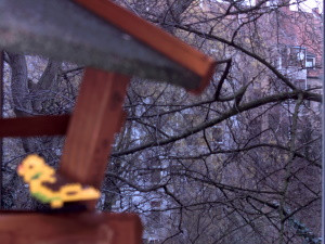
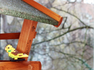
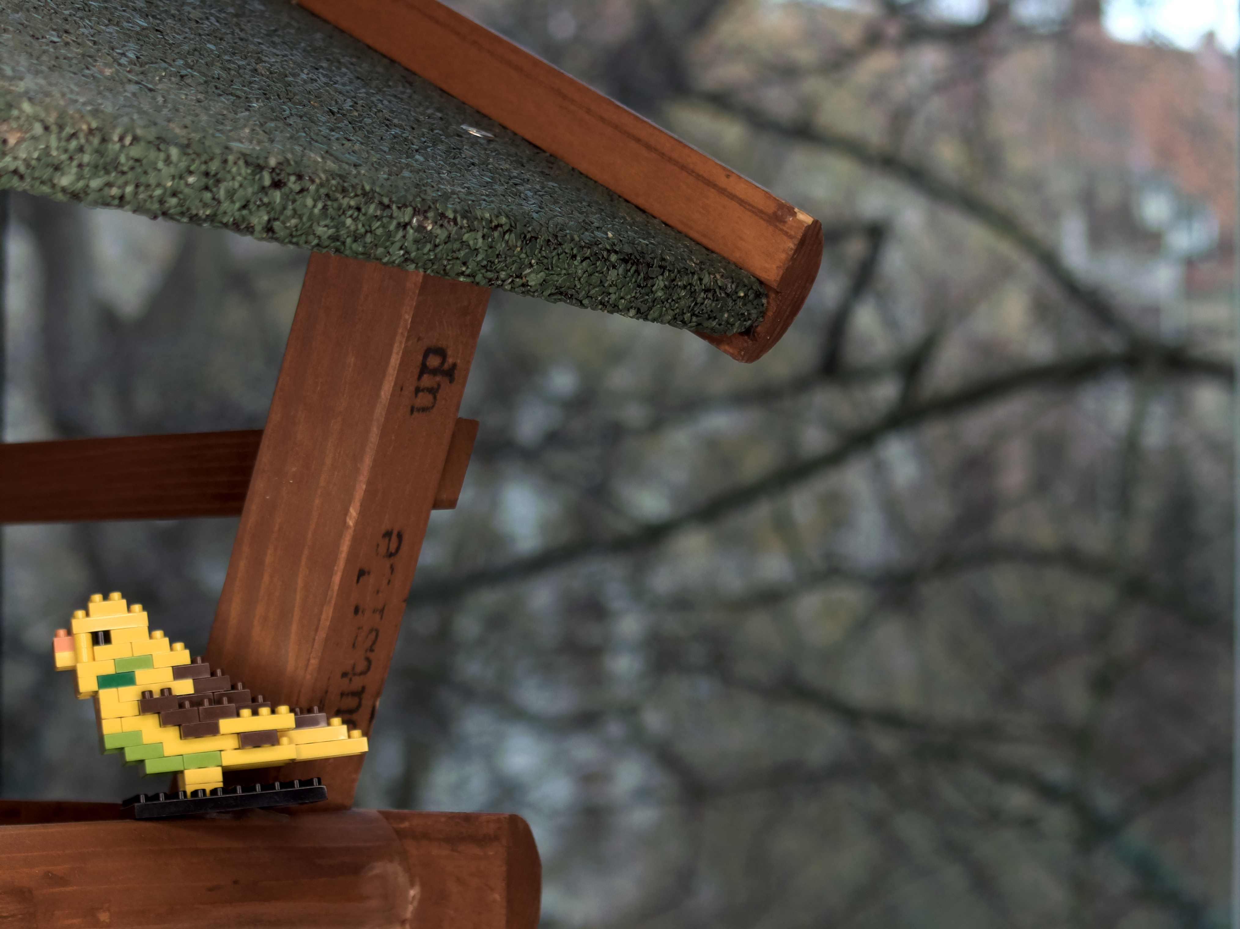
This is the first part of this article series about Project JiJi. In this article, I described the steps to build and mount the hardware, flash the M5Stack, and start the Microservices application on the Raspberry Pi 4. The software components are still buggy and in optimization processes, but they have started to produce some outputs :). You can check and download the sample photos (Fig. 11 to 14). The HDR files (
/FORMAT=32-bit_rle_rgbe) were processed using Luminance HDR v2.6.0.One more thing: If you want to cooperate on this project, you're really welcome to do so and please contact me!
We use cookies to improve our services. Read more about how we use cookies and how you can refuse them.
")


")


")

 in Chromium")

Empty